The mechanical lifts are extended through a rack and pinion system or power screw both of which can convert rotational motion. Selection procedures and examples are given.
2
3 Acknowledgments In performing our senior project we had to take the help and.
. Motor Sizing Calculations This section describes certain items that must be calculated to find the optimum motor for a particular application. GEARS AND PULLEY SYSTEMS. CLICK BELOW FOR APP.
Cam-Follower Slider-Crank Rack-Pinion etc. All the electric lifts are mechanical. It is common practice to design the linkage system so that the movement of all of the bodies are constrained to lie on parallel planes to form what is known as a planar linkageIt is also possible to construct the linkage system so that all of the bodies move on concentric spheres forming a spherical linkageIn both cases the degrees of freedom of the link is now three rather than six.
One of the disadvantages to using circular pitch rack and pinion is that the mounting distance of the pinion in relation to the pitch line of the gear rack will not be round number. Selection Procedure First determine certain features of the design such as drive mechanism rough dimensions distances moved and positioning period. Using our previous examples the module 25 20 tooth pinion would be set at 25mm above the pitch line of the rack whereas the CP10 20 tooth pinion would need to.
Input the center distance between the pinion and the gear. Input the number of teeth of the pinion and the gear. Manufacturing of the improved wiper will be carried out.
The benefit of mechanical lift is that the teeth of its gear system prevent from. Spur Gears and Simple Gears Gear Trains and Idler Gears Drawing Gears Compound Gears Rack and Pinion Bevel Gears Worm Gears Gears and Calculations Pulley Systems Belt Drive Pulley Calculations. Or a combination of these mechanisms will be explored used to achieve the goal of this project.
The collimeter C consists two hollow concentric metal tubes one being longer than other. If needed also input the gear cutting tools tip rounding radius coefficient. At the beginning the project needs to achieve the design and some analysis of wiper mechanism.
Click here for Smart Learning Sheets on Gears and Pulley Systems. The smaller tube is provided with a slit at the outer end and can be moved in our out the longer tube with the help of rack and pinion arrangement. Enter the precision grades of the two gears as well as absence or existence of tooth form corrections.
The longer tube carries an achromatic lens L at one end and the smaller tube at the other end.

Worm And Wormgear Design Equations And Calculator Mechanical Design Design Worms
2

Me 340 Modeling Of A Rack And Pinion System Youtube
2

Automatic Transmissions Use Planetary Gear System To Operate Description From Mekanizmalar Com I Searched For This Gears Transmission Mechanical Engineering
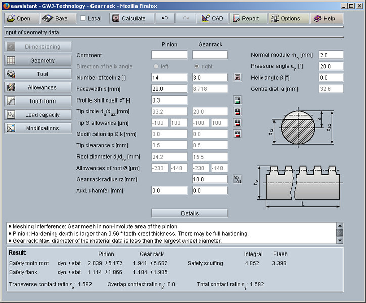
Gwj Eassistant Rack Pinion Gear Pairs According To Din 3990 Iso 6336 And Further Standards
2
2
0 comments
Post a Comment